Analysis
Fall 2019
The design requirements for the engineered system are as follows:
Must weigh less than or equal to 15% of the drone’s total weight (3-lb); thus, less than 7.2-oz (within ±0.1-oz).
Payload release mechanism must be able to be tripped purely mechanically by the drone's built-in camera (80% success rate).
Must be mounted onto a commercial drone without any modifications to the drone itself.
Mounting and removal of the system does not require any hand tools.
The payload release mechanism cannot be activated by any single action; there must be multiple inputs by the user to activate it (80% success rate).
The system must be able to release the payload when the drone is landed (80% success rate).
The system must be able to release the payload when the drone is in flight (80% success rate).
The drone’s power + the structural integrity of the system must be able to carry packages ≤ 1.25-lb.
The payload storage system must be able to hold cardboard boxes with sizes in the range of 3x3x3” to 8x6x3”.
The system’s structural integrity must be able to withstand the horizontal drag force incurred by the maximum size payload (8x6x3”) when traveling at the drone’s maximum speed (35-mph).
The payload system must be able to retain/grip packages when the drone is traveling at max speed (35-mph) (75% success rate).
What kind of analysis?
The analyses can be divided into three main categories:
Structural Strength
Kinematic
Mechanical Design
Structural strength analyses were used to size components and optimize them to be lightweight. Classical beam equations (i.e. σ=Mc/I & τ=VQ/It, etc.) were used to determine stresses (direct shear, direct normal, bending, and transverse shear) and then size dimensions accordingly. FEA (finite element analysis) software was used to validate analyses & further optimize parts for light-weighting. Some parts analyzed include the grappling arms, which must hold the package's weight and withstand clamping forces.
Kinematic analyses were used to determine geometric constraints (i.e. range of motion between two moving parts) and the amount of torque required to rotate each moving linkage. For example, the frictional force caused by the weight of the package on the grappling arms was used to determine the minimum torque that a spring must exert on the shaft to open the arms.
Mechanical design analyses were used to size bolts and springs and to determine appropriate fits between parts. Mott's Machine Element's in Mechanical Design was used as the primary reference for these analyses (Ch. 13, 18 & 19). In the case of screws, thread bearing area and minimum effective length was used to design against tear-out (metal threads in plastic).
If you want to review each of the analyses in detail, Click Here to Go to the Report and go to Appendix A to see a complete list.
Analysis Highlight
Grappling Arm Structural Optimization (Analyses B & U)
Intro:
One of the most important parts in the system are the grappling arms, of which there are 6. The purpose of these parts is to hold and release the payload. Like all of the parts, they had to be optimized for a maximum strength-to-weight ratio. Not only that, but they had to have the correct geometry to store and subsequently release various payload sizes. The design for the grappling arms was performed in Analyses B & U.
Analysis B focuses on structural strength analysis and weight optimization. It was done completely using manual calculations.
Analysis U is the corresponding Finite Element Analysis (FEA) of the design produced in B. Additionally, some further weight optimizations were made that would have been too complicated to calculate manually.
Requirements:
The requirements targeted in these analyses were 8 & 9, which state that the system must be able to carry packages up to 1.25-lb and that the system must be able by able to hold cardboard boxes with sizes in the range of 3x3x3” to 8x6x3”.
Analysis B
Summary
The maximum package size was used to create the major dimensions. The grappling arm was determined to be an “L” shape. On the bottom face, the weight of the package was exerted; on the side, the reaction to the package clamping force was exerted. Free body diagrams were created of multiple sections of the leg. Reactions were subsequently solved for, and then shear and moment diagrams were created. The cross section of beam BC was optimized to meet the allowable stress in the material. Deflections were calculated and determined to be too large (though still under yield), so the beam was enlarged according. This beam size was then applied to beam AB. The normal stress was within the allowable, but the deflection was too high. The beam size of AB was subsequently increased. The design was then optimized for weight, and stress concentrations were considered.
Click on the slide deck to the right to see full-size images of the green sheets with additional info:
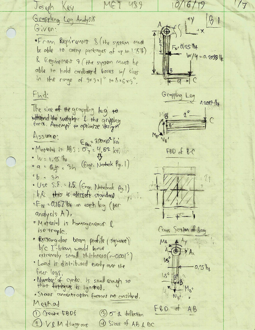
Creating FBD's of sections, splitting the arm into the vertical (AB) and the horizontal (BC) lengths, preparing them to be treated as cantilevered beams.
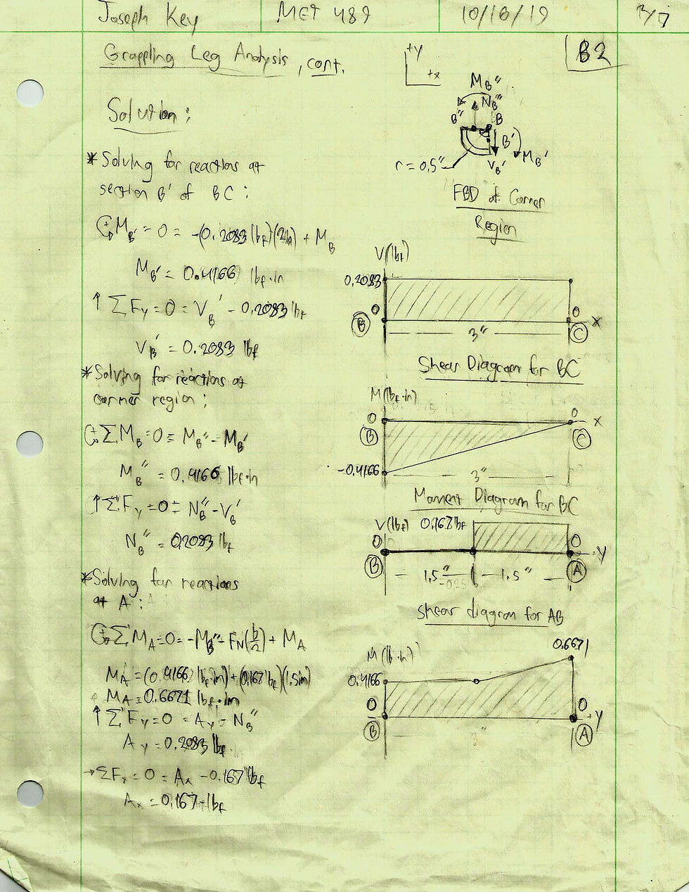
Creating shear and moment diagrams for AB & BC and solving for the reaction forces and moments at the sectioned planes.

Using maximum stress in BC to solve for the minimum required size. Increased size to reduce deflection so that it would not exceed 1/2 of the section width.
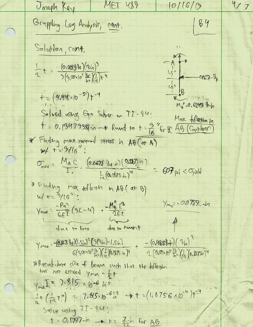
Applying cross-section from BC to AB and checking stress and deflection. Deflection was too high, so constraining it to the same parameter as BC (1/2 the section width) produced a larger cross section.

Optimizing BC so that the maximum stress is uniform throughout, reducing weight. This calculation produced an exponential function that was used to plot the shape of BC.
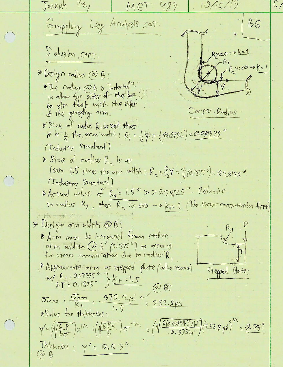
Increasing the filleted corner between AB & BC to reduce stress concentrations and increasing the section width to account for the remaining concentration. This was an effort to produce a uniform stress throughout the entire grappling arm.
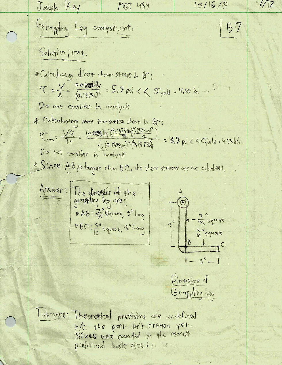
Calculating direct and transverse shear stress as a double-check, although these values were far below the acceptable stress value. The final dimensions of the grappling arm are shown.
Analysis U
Summary
From Analysis B, the basic dimensions were determined. First, the grappling arm was subjected to fixed constraints at its hinged end, which represented the arms being locked and unable to move. A global mesh was applied such that the element size did not exceed ½ of the smallest feature size. A load (representing the package weight) was applied at the very end of the arm, to represent the worst-case scenario of a small, heavy payload. From this, the results of stress and deflection were obtained. Using these results, material was removed from beam AB, changing its profile from a square to a modified I-beam. The same boundary conditions, mesh settings, and loads were applied, and the analysis was rerun. All FEA was performed using Solidworks Simulation.
Click on the slide deck to the right to see full-size images of the FEA results with additional info:

Finding von Mises stress. The maximum value was located at the corner of the "L" shape.

Finding deflection. The maximum value was located at the free end of the arm.

Creating the mesh for the FEA model. The mesh size was such that it did not exceed 1/2 of smallest feature size.

Finding von Mises stress with the optimized shape (lightening cuts in length AB). The maximum value was uniform along the outer surface of BC and was 15% greater than that of the original design.
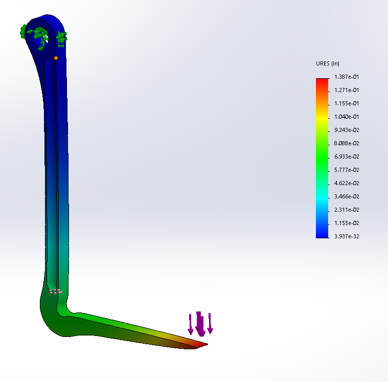
Finding deflection for the optimized design. The maximum value was located at the free end of the arm and was 17% greater than that of the original design.

The results. The optimized design had 17% more deflection, 15% more stress, and 21.5% less weight. Since the values were still below the allowables, the optimization was successful.