Construction
Winter 2020
As 95 of the 161 total parts are plastic, the primary method of manufacture is FDM (Fused Deposition Molding) 3D-printing, using the Creality CR-10S Pro 3D owned in the department.
All metal parts (screws and springs) were purchased from McMaster Carr
The first 3D-printed parts were made with ABS. The first layer of the prints was the most difficult to accomplish, as the thin filament would not stick to the bed. One contributing reason was the fact that the bed was not properly leveled. This issue was mitigated in part by manually changing the Z (vertical) offset of the extruder head for the first few layers.
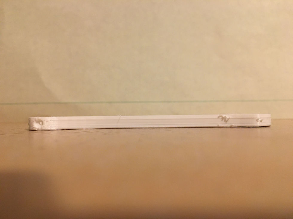
After removing the parts from the bed, they instantly acquired a noticeable bend. This issue of undesired warpage is very common for 3D-printed ABS parts that are not in a temperature-controlled environment. See the 1st image in the slide deck.
The next step taken in the 3D-printing process was to change the material from ABS to PLA. PLA has a much lower operating temperature (around 180 to 200 instead of 230 to 260 degrees Celsius) and does not require a heated bed. This means that the occurrence of residual stresses was no longer an issue. See the 2nd image in the slide deck.
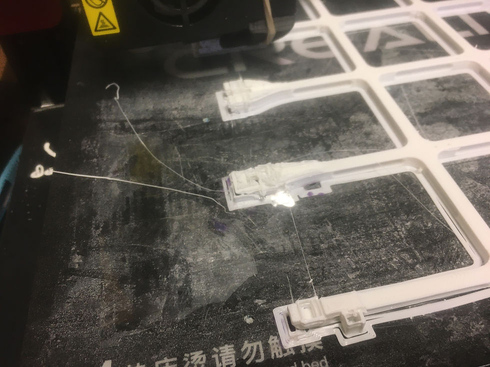
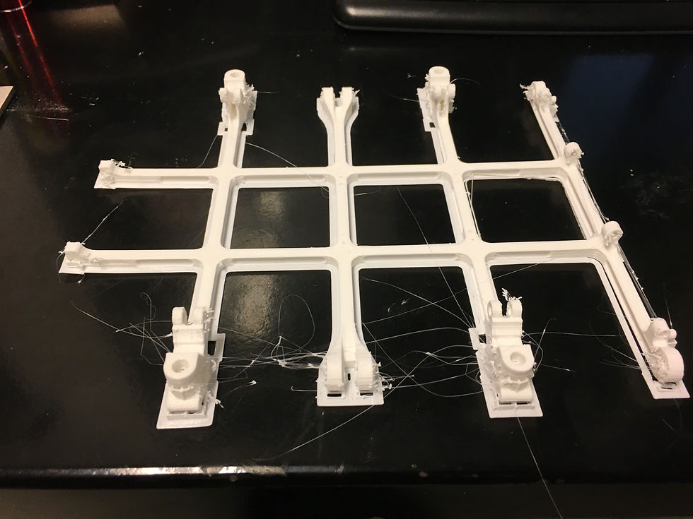
However, since the bed is not heated, PLA can be more challenging to adhere to the bed. To solve this issue, the principal engineer experimented with using rafts as a form of adhesion, rather than brims. Additionally, the temperature of the heated bed was raised to 40 degrees Celsius, which allows the first layer to adhere better. This was successful, and many parts were printed simultaneously without incident. See 3rd image in the slide deck for an example.
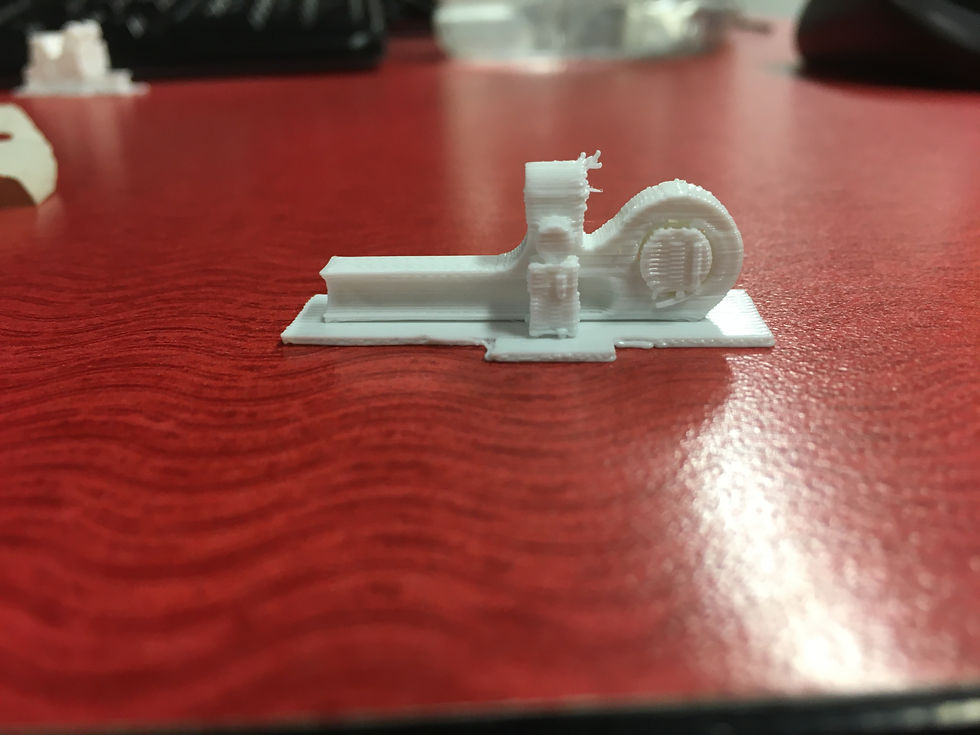
Once the printer settings were optimized, small parts could be printed consistently and with great precision. See 4th & 5th images in the slide deck.
The only plastic parts not 3D-printed were the grappling arm shafts. Instead, these were constructed from 1/4" ABS round stock. A drill press was used to create the holes perpendicular to the shaft's longitudinal axis. See 6th image in the slide deck.
The final assembly was 95% constructed as of 2/28/20. See 7th image in the slide deck.
The final assembly was 100% completed as of 2/30/20. See 8th image in the slide deck.

An ABS grappling arm that experienced warping due to the uneven temperature distribution
The same part as shown previously, except that it was printed using PLA.
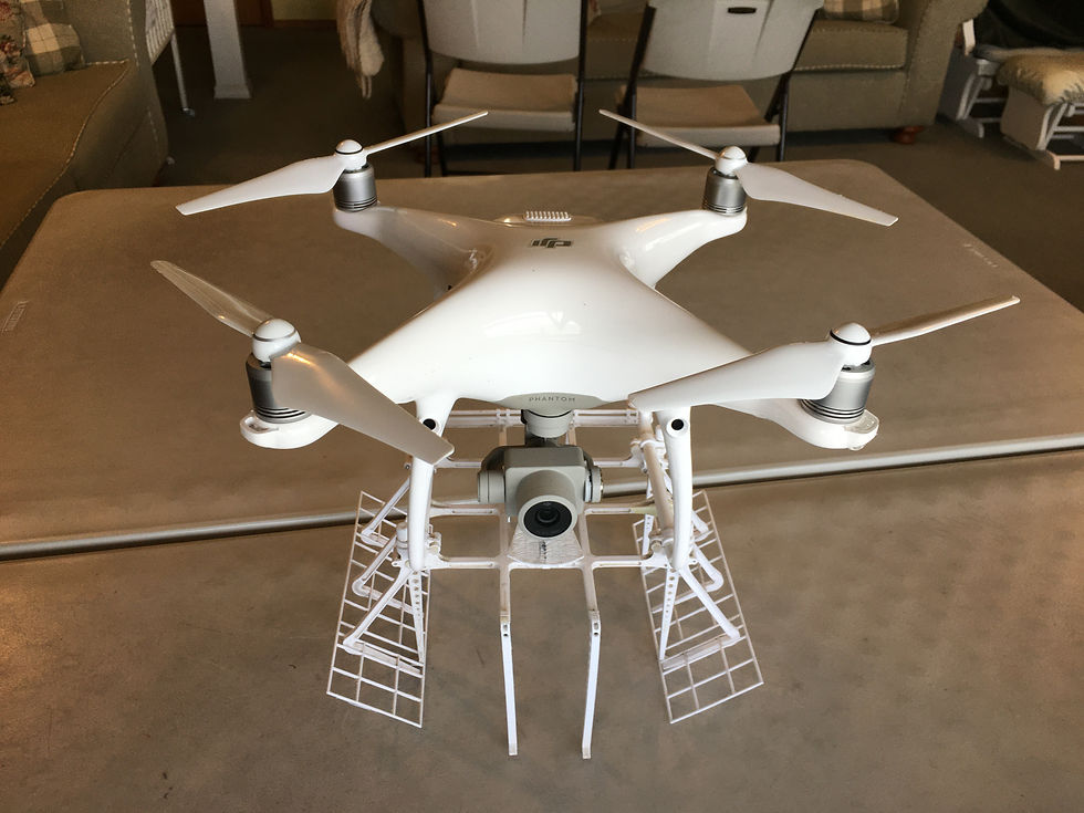
100% completed and mounted assembly
An ABS grappling arm that experienced warping due to the uneven temperature distribution
Construction Timelapse
Manufacturing Highlight
Structural Frame 3D-Printing and Processing
Intro:
One of the most important parts in the system is the structural frame, which serves as the mounting point for all of the other components. As such, it is the largest part in the project.
The frame was 3D-printed as a single part on the Creality CR-10S Pro.
All mounting points (holes, threads, slots, etc.) needed to be post-processed after 3D-printing.
Requirements:
The requirements targeted in this manufacturing process were 1, 8, & 10, which pertain to minimizing weight below 7.2-oz and having the structural strength to be able to carry packages up to 1.25-lb at high speeds, respectively. These are related to the 3D-printing process, which allows for lightweight plastic to be used and optimized using complex geometry not possible in traditional manufacturing. Additionally, the 3D-printed layer properties are integral to structural strength.
Structural Frame
Summary
The frame was initially designed to have a large flat surface, allowing it to be 3D-printed as a single part. This was done to drastically improve the rate of manufacture. The first approach was to print using a raft, a layer of plastic underneath the part to improve bed adhesion. However, this took very long (~3 hours) and still did not adhere, so it was abandoned. Next, the frame was printed using a brim, a layer of plastic around the edges of the part. Adhesion was good; however, the small features of the parts were unable to be printed because they were too small and had no supports. To remedy this, some of the features were enlarged, and support structures were added. Small samples of the problem regions were printed and found to be successful. Subsequently, the entire frame was printed with these settings. However, the print failed several times, as adhesion kept being lost. Even the application of glue and tape to the print bed did not stop this problem. Finally, after after many tries, the frame printed successfully, with only minimal loss of adhesion in a small area. This resulted in the part being slightly misshapen in that area, but it was not significant enough to prevent part assembly.
Subsequent to printing, all of the mating features (holes, threads, slots, etc.) were post-processed manually by drilling, reaming, tapping, and filing. It was initially thought that the 3D-printer could achieve acceptable tolerances, but this was not the case.
Click on the slide deck below to see full-size images of the process with additional info:

Printing the raft. It did not end up being used, as it took very long to print and did not improve adhesion.

The failed print. The fact that no supports were used and the fact that the features were much too small was the likely reason for this failure.
Closeup of the failed print.

Improved design printed with support. This proved to be successful, and the settings were applied to the entire 3D-print.
Another small feature with added support.

Using tape to promote adhesion. This was very inconsistent, as sometimes the part separated from the tape. In other cases, the tape separated from the bed. However, after a few attempts, it did prove to be largely successful.
The final, successful part. Note the lack of adhesion on the far-left feature caused it to be slightly misshapen.